 |
 |
 |
 |
 |
 |
 |
| Reconditioning the
Silver Shadow fuel pump |
|
| Removal of fuel pump from car |
|
 |
 |
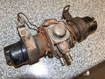
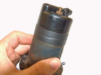
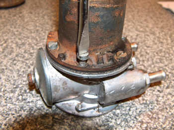
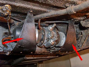
| The fuel pump on the
Silver Shadow is located almost directly below the driver seat, under
the car. This is the pump on SRH19461, my 1974 Silver Shadow. |
Just to keep matters
civil and tidy I gave it a good clean with a brush and pressure washer
before commencing with removal of the pump from the car. |
 |
 |
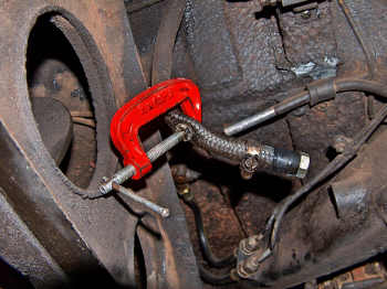
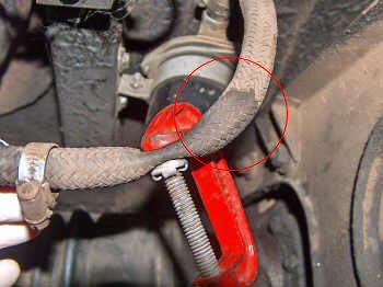
| First thing to do is to disconnect the battery leads, and then to block the fuel supply to the pump. I blanked off the outlet pipe from the fuel filter because it was accessible and towards the rear of the vehicle, away from where I had to work on the fuel pump. My method of blocking the fuel supply probably results in a destroyed fuel pipe, so this pipe will be replaced during reassembly. | In order to avoid confusion during assembly, clearly mark the upper delivery pipe and lower feed pipe with some tape. |
 |
 |
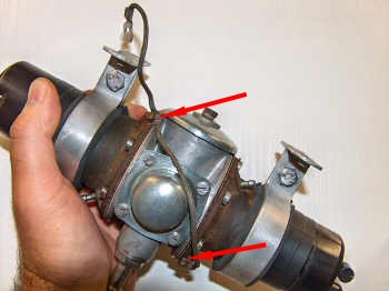
| Remove the feed and delivery pipes from the pump. | Remove the two stone guards. They are held in place by four screws each. |
 |
 |
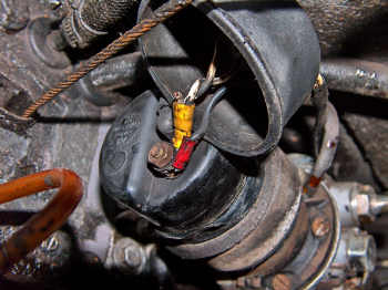
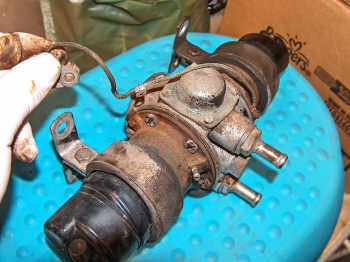
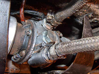
| Remove the rubber covers from each end of the pump, and disconnect the electrical wires. | Disconnect the two breather pipes from either side of the pump body. |
 |
 |
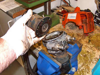
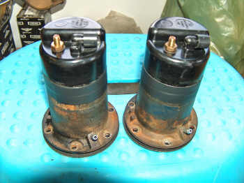
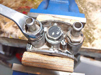
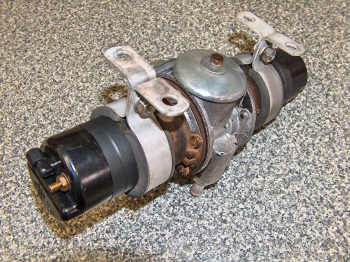
| Remove the four nuts that secure the pump to the body member and remove the pump. | Out of the car and onto the bench! |
| Disassembling the fuel pump |
|
 |
 |
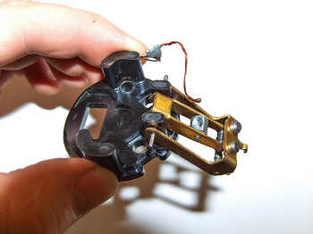
| Remove the two screws that secure the earth lead to the pump and remove the earth lead. | Slide the two mounting brackets off the pump. |
 |
 |
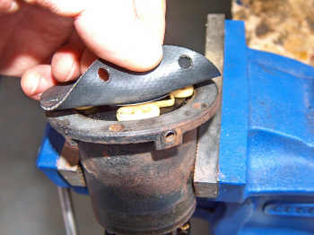
| Remove the six setscrews that secure the coil housing to the pump body... | ...and gently withdraw the coil housing from the pump. |
 |
 |
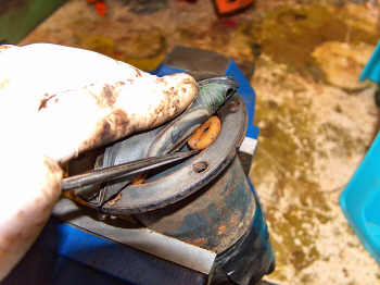
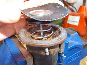
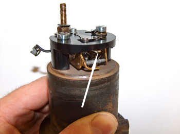
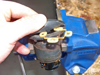
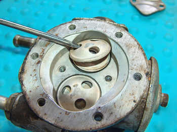
| Remove the nylon
guide plate by turning back the edge of the diaphragm and carefully
probing it with a screwdriver to lift the two ends out of the recess
into which it fits. (NOTE: On earlier cars there are eleven brass rollers in place of the nylon guide plate) |
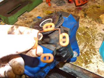
The nylon guide plate
removed from the coil housing. |
 |
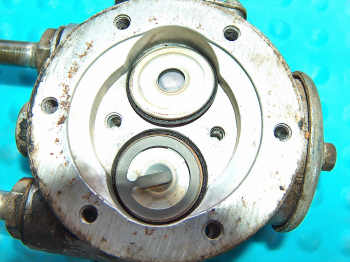
Remove the diaphragm
and spindle by unscrewing it anti-clock-wise until the armature spring
pushes it away from the coil housing. |
 |
|
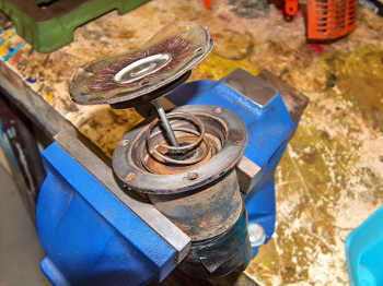
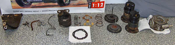
| The disassembled pump
is now ready to be reconditioned. |
|
| Reconditioning the coil housing |
|
 |
 |
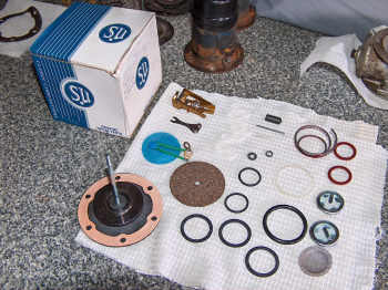
| The reconditioning
kit (Part number EPK 305) is supplied by Burlen Fuel Systems
www.burlen.co.uk (You will need two kits) |
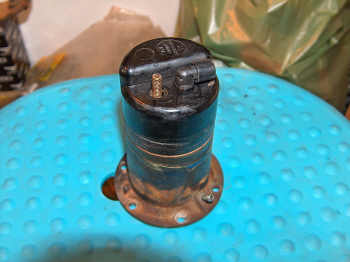
The coil housing ready to be disassembled. |
 |
 |
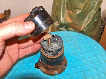
| Start by removing the bakelite end-cover. | Remove the end-cover seal washer from the terminal stud. It will be replaced, so don't worry about preserving it. |
 |
 |
| Remove the nut from the terminal stud. | Remove bolt that secures the contact blade, and remove the contact blade. |
 |
 |
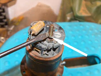
| Remove the two bolts
that secure the pedestal to the coil housing. |
Remove the remains of
the lead washer from the terminal stud, and then remove the terminal
tag. |
 |
 |
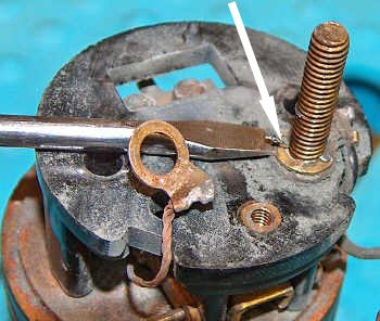
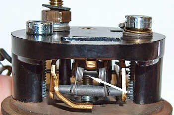
| With the pedestal now
separate from the coil housing invert it and remove the pin that
secures the rocker mechanism. |
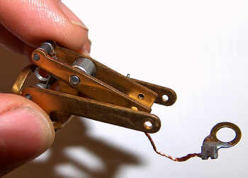
Hold the replacement
rocker mechanism as shown in the photograph above. Note that the inner
rocker is positioned above the outer rocker with the contact points
pointing downwards. |
 |
 |
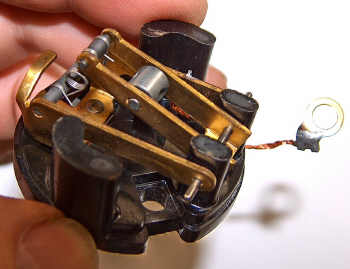
| Using the new pin
from the kit, secure the new rocker mechanism to the pedestal. |
Push the inner rocker
downwards so that it assumes the position shown in the photograph
above. It will "click" into place. |
 |
 |
| It is very important
that the rocker mechanism is free to swing on the pivot pin and that
the arms are not binding on the legs of the pedestal. If necessary the
rockers can be squared up with a small pair of thin-nosed pliers. |
Swing the rocker
mechanism out of the way and insert the square-headed terminal stud as
shown in the photograph above. |
 |
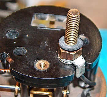 |
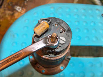
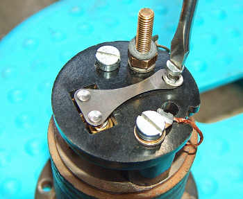
| Turn the pedestal
right way up and put the spring washer onto the terminal stud, followed
by the terminal tag (electric connection), then the new lead washer and
finally the coned nut with its coned face to the lead washer. |
Tighten the coned nut
and add the new end-cover seal washer. |
 |
 |
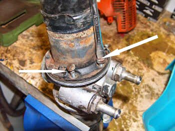
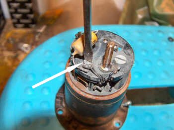
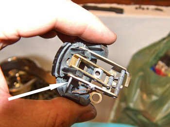
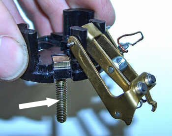
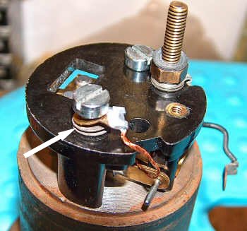
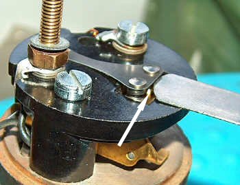
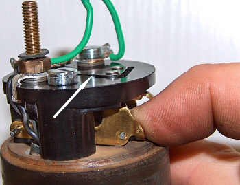
| Assemble the pedestal
to the coil housing. Ensure that the spring washer on the left-hand
bolt is between the pedestal and the earthing tag (see arrow) |
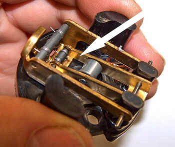
Invert the coil housing and place the armature spring in the recess with its large diameter towards the coil. |
 |
 |
| Make sure that the small neoprene impact washer is in place. | Fit the new diaphragm by inserting the spindle into the hole in the coil... |
 |
 |
| ...and screwing it
into the threaded trunnion in the centre of the rocker assembly
(arrowed). Hold the coil housing in the left hand in an almost
horizontal position and screw in the diaphragm by pushing with the
right thumb and turning it clockwise at the same time. Keep pressing
and releasing the diaphragm and screw it in until the rocker just
"throws over". |
Fit the new contact
blade to the pedestal. This is a temporary assembly just to set up the
rocker mechanism, so do not worry about the electrical connections at
this stage. |
 |
 |
| Check the lift of the
contact blade tip above the top of the pedestal with a feeler gauge... |
...bending the upper
stop finger beneath the pedestal to achieve a gap of 0.9 mm |
 |
 |
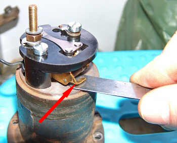
| Check the gap between
the lower rocker finger and the coil housing with a feeler guage
bending the stop finger (arrowed) to achieve a gap of 2.3 mm. Once
complete remove the
contact blade again. |
Hold the coil housing
in the left hand and again turn the diaphragm, this time more
accurately, until the rocker just
"throws over". |
 |
 |
| Now turn the
diaphragm back (anti-clockwise) to line up with the nearest hole and
then again a further four holes (two-thirds of a complete turn). The
diaphragm is now correctly set. |
Fit the armature
guide plate, flat face towards the diaphragm, by turning back the
rubber edge and carefully inserting
an end lobe first into the recess. |
 |
 |
| Once you have
carefully fed the guide plate into position ensure that each lobe is
pressed firmly into the recess. Be careful not to distort the delicate
connecting arms between the lobes. |
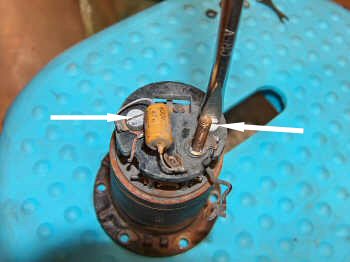
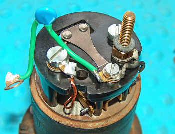
Fit the contact
blade, coil lead and resistor (or condenser is some cases) to the
pedestal. |
 |
 |
| Fit the other end of
the resistor to the pedestal screw. |
Ensure that the
spring washer is between the pedestal and the earthing tag. |
 |
 |
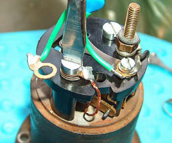
| Adjust the contact
blade so that the contact points are a little above (ahead) of the
contact points on the rocker when the points are closed. |
Check that when the
lower rocker is pressed down onto the coil housing the contact blade
rests on the narrow ridge which projects slightly above the main face
of the pedestal. If it does not loosen the contact blade attachment
screw, swing the blade to the side and bend it downwards in order to
adjust it until it rests on the ridge. (Do not over-tension it as that
will restrict the travel of the rocker mechanism) |
 |
 |
| Clean the bakelite
end cover and make sure that the one-way valve works as intended by
blowing out through it from the inside. Air must be able to exit the
housing, but should be restricted from entering. |
Tuck all electrical
cables into position so that it cannot foul the rocker mechanism, and
fit the end cover to the coil housing. Fit the lock washer, and secure
with the brass nut. Insulate with electrical tape (insulation tape) |
 |
|
| Repeat the entire
process on the remaining coil housing. |
|
| Reconditioning the pump |
|
 |
 |
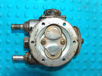
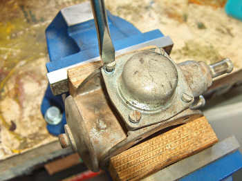
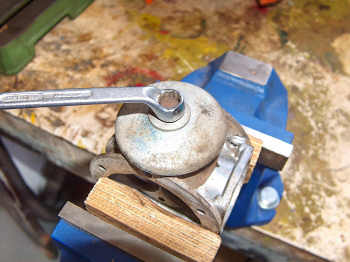
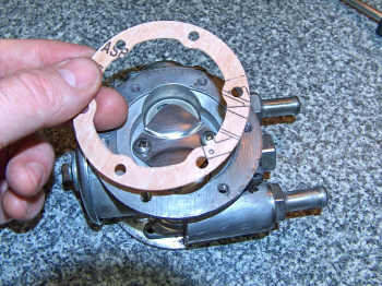
| The pump, dirty and in need of attention. | Start by removing the
clamping plate. |
 |
 |
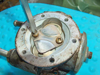
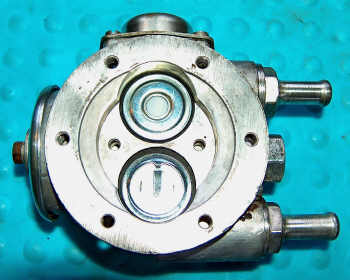
| Remove the two valve
covers. |
Remove the two
valves, taking note of their orientation. |
 |
 |
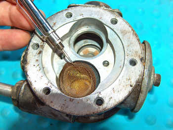
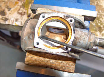
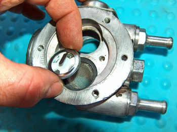
| Remove the filter and
sealing washer. Repeat the last four instructions on the other side of
the pump. |
Remove the air bottle
cover. |
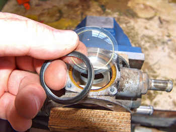 |
 |
| Remove the sealing
ring and diaphragm. |
The washer below the
diaphragm is very delicate and might have to be scraped off. |
 |
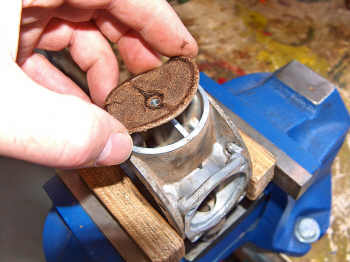 |
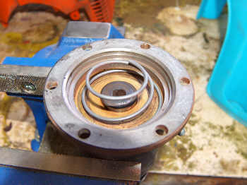
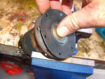
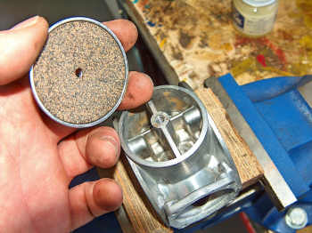
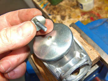
| Remove the dished
cover from the rear of the pump. |
Remove the cork
washer. |
 |
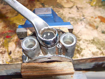 |
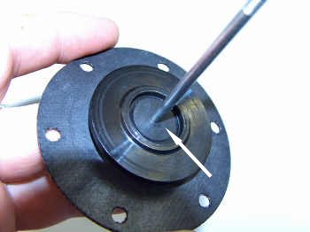
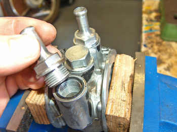
| Remove the in and
outlet nozzles and their sealing rings. |
Remove the central
plug and sealing ring. |
 |
 |
| Clean all the
components of the pump and reassemble starting with the central plug
and in-and-outlet nozzles. Remember to fit the new sealing rings. |
On the rear of the
pump fit a new cork washer and... |
 |
 |
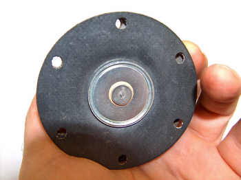
| ...replace the dished
cover. Note the orientation of the washer which is shaped to fit onto
the dished cover. |
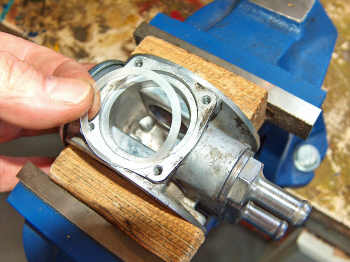
Moving on to the top
of the pump fit a new joint washer into the recess. This washer is
almost transparent and very delicate, so take care with it. |
 |
 |
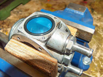
| Carefully fit the new
domed diaphragm and sealing ring. |
Replace the air
bottle cover. |
 |
 |
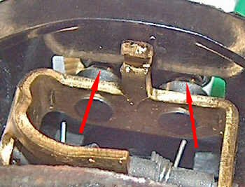
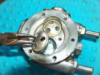
| Replace the filter
and valve assembly's using new sealing washers. |
Note the correct
orientation of the valves. This is critical for the correct operation
of the pump. |
 |
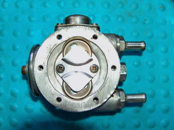 |
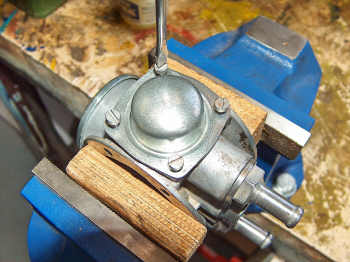
| Replace the two valve
covers and... |
...finally replace
the clamping plate, and repeat on the other side. That concludes the
overhaul of the pump. |
| Reassembling the fuel pump |
|
 |
 |
| Fit a new joint
washer and... |
...bolt the solenoid
housing back on to the pump body. Repeat on the other side. |
 |
 |
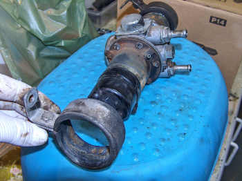
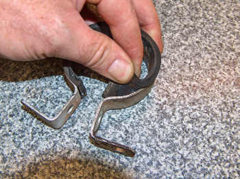
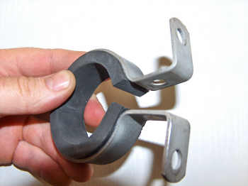
| Replace the old rubber insulation from the mounting clamp. | I had to soak mine in
thinners to soften the old rubber before I managed to
successfully remove it. |
 |
 |
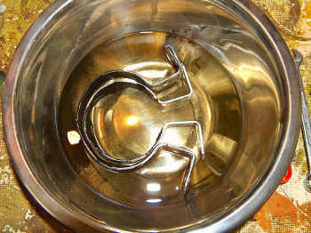
| The rubber insulation
can be bought from most hardware stores. It is very important to
replace it to avoid excessive transmission of noise from the pumps. |
Make sure you line
the brackets up before tightening. It helps to measure the distance
between the mounting holes on the car in order to accurately position
the brackets. |
| Fitting the fuel pump | |
 |
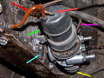 |
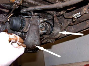
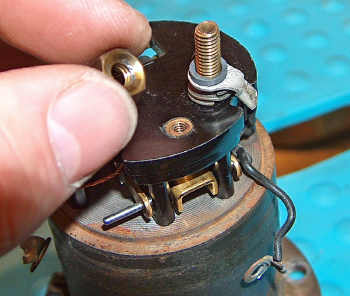
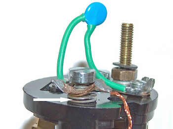
| Attach the earth lead
to the pump body. There are two mounting points, arrowed above. |
Fit the fuel pump
unit by following this sequence: 1. Check that the
mounting brackets line up with the holes, and adjust if necessary. Do
not mount the pump yet.
2. Propping the pump
up with one hand, connect the right-hand side electric lead to the coil
housing (yellow arrow)
3. Attach the two
upper breather pipes to the nipples on either side of the pump body
(pink arrow)
4. Bolt the pump in place remembering to attach the earth lead (green arrow) and the radio interference suppressor (blue arrow) 5. Connect the left-hand side electric lead and radio interference suppressor lead to the coil housing (orange arrow) 6. Attach the breather pipe into the rubber end cover on both sides (red arrow showing left-hand side only) |
 |
 |
| Fit the two stone guards. | Fit the feed and delivery pipes to the pump. The lower pipe is the feed pipe (from the fuel tank) and the upper pipe is the delivery. |
 |
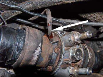
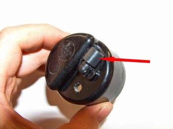
At this point you can
reconnect the battery and start the car to test the fuel pump. With the
engine running put a finger gently against the solenoid housing on the
pump. You will feel a continuous, gentle "thump" as the the rocker "throws
over". Check both sides. |
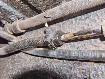
| Remove the block you
put on the fuel line. This pipe had to be replaced because the
disturbance caused it to weep. |
|
|
|
| Check all the fuel
lines for leaks. With the increased pressure of the newly reconditioned
pump some of the old pipes are likely to start leaking. |
|
| Should you need to replace the whole pump
the part number for the original SU pump is AUA 8. However, Burlen also
now supply an electronic version of the same pump that does away with
the points, part number AUA 8 EN. Either of these pumps can be ordered
from www.burlen.co.uk |
|
| Return to Maintenance
index page |
|